-40%
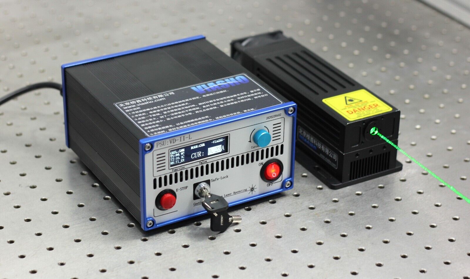
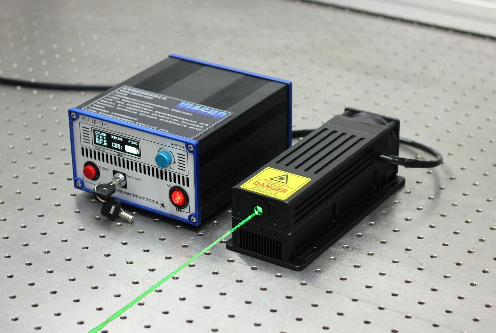
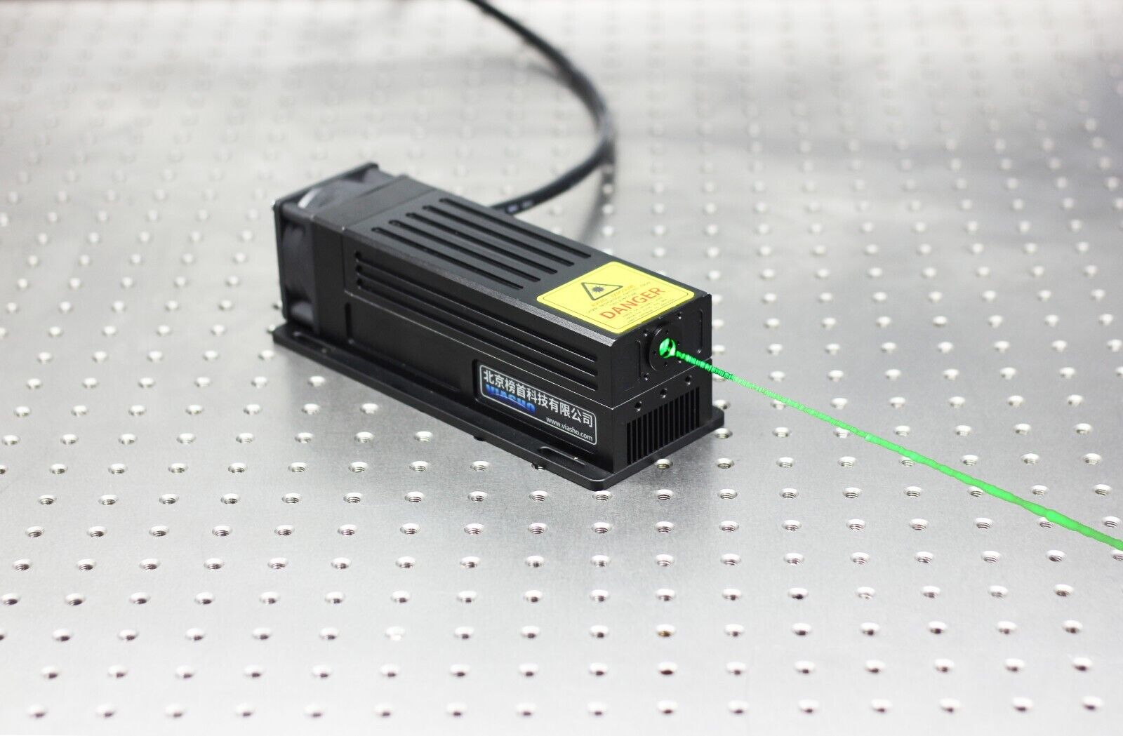
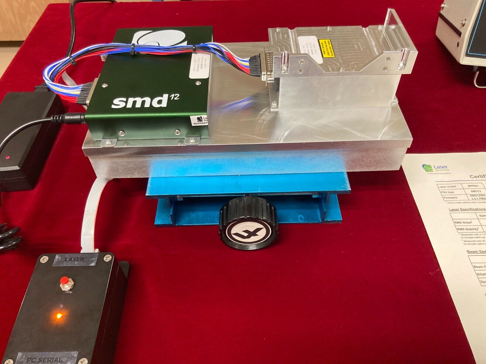
Viasho 532nm 4W green laser,both TTL/analog mode, stable output, bright
$ 1477.87
- Description
- Size Guide
Description
This is a compeleted new4
W green laser. And we make some new design and change the power supply to a digital version which can supply better modulations and make the laser more stable.
OK.If you have any question,please leave a message,then I will answer you in time.
Please see specs below:
Wavelength (nm)
532
Output Power (mW)
4000
Working Mode
CW
Beam Mode
Transverse
TEM00
Longitude
Multi-longitude
Spectral Linewidth (nm)
<0.1
Polarization
Line polarization
Polarization Ratio
>100:1
Beam Quality (M2 factor)
<1.2
Beam Divergence (full angle, mrad)
1.5
Beam Diameter at Aperture (mm)
2.5
Beam Roundness
>90%
Power Stability (RMS, over 8 hours)
<5%
Aperture Position (mm)
50
Laser Head
Dimensions (L×W×H, mm)
205x60x50
External Modulation
5V TTL/5V Analogue
Modulating Repetition
30KHz TTL/10KHz Analogue
Cooling System
TEC
Warm-up Time (minutes)
<15
Operation Temperature (
℃
)
18~30
Expected Lifetime (hours)
>10000
Warranty Time
1 year
1.
Product
VA series laser driver power supply with high power semiconductor laser constant current drive, dual TEC temperature control and system monitoring functions, which uses a constant-current PWM closed-loop laser driver, PWM temperature control and intelligent MCU central control system, so as to LD lasers provide efficient and reliable drive and temperature control, suitable for driving a variety of air-cooled solid-state lasers or laser module.
1.1.
Feature
Ø
PWM constant current technology, more efficient
Ø
TEC dual output, flexible and accurate temperature control
Ø
overheating, over
current, overvoltage, soft start multiple protection
Ø
A key jog buttons, the user interface is simple and easy to operate,
Ø
S
mall size, light weight
Ø
I
nternal / external control mode selection
1.2.
Specification
Model
VD-IA
/ VD-1B
LD drive current
0
~
10A
LD voltage
2
~
18V
adaptive
Modulation
Continuous / analog (external control) / Digital (external control)
TEC Temperature Range
16.0
~
28.0
℃
TEC maximum drive voltage
20V
Maximum drive current TEC
6A
Rated voltage
90
~
240V AC
Operating ambient temperature
-10
~
45
℃
Dimensions (L × W × H)
168mm
×
16
4mm×
80mm
Total weight
2.0kg
1.3.
Dimensions
(mm)
1.4.
Front view
1
Vents
,
for ventilation;
2
Display options
,
two green LED digital display, such as C1
.
3
V
alues
,
three red LED digital display, such as 5.58
.
4
Rotary
S
witch
, y
ou can smooth, counterclockwise rotation of options selected performance parameters change
, p
ressing the mode selection.
LED display mode
follow as,
(1) Normal mode,
screen never
blink, turn counterclockwise options forward flip, back flip clockwise options. Press once to enter the setup mode or exit the setup mode.
(2)
S
etting mode, the value
is
blink
ing
, turn counterclockwise
or
clockwise to reduce
or increase
property value.
(3)
A
larm mode
,
options flashes and displays the corresponding property value. Rotary switch temporarily lapsed in this state.
Detailed display described later.
1.5.
Back view
1
DB15 (pin) Interface
, connect to
the laser
head.
2
Cooling fan
for
ventilation
.
3
DB15 (hole) interfaces
,
external control signal input;
4
T
hree-pin
p
ower
socket (L, N, PE).
5
Interlock, safety lock protection.
6
Power switch: on / off external power supply.
Interface definition
as follows.
(
1
)
DB25
Interface
definition
No.
Pin name
Description
No.
Pin name
Description
1
LD1+
L
aser positive
14
LD1+
L
aser positive
2
LD1+
L
aser positive
15
R
t
2-
T
hermistor
2
negative
(Internal ground)
3
Fan-
Fans negative
16
Rt2+
T
hermistor
2
positive
4
TEC2-
C
ooler
2
negative
(Internal ground)
17
TEC1-
C
ooler
1
negative
(Internal ground)
5
TEC2-
C
ooler
2
negative
(Internal ground)
18
TEC1-
C
ooler
1
negative
(Internal ground)
6
NC
No connection
19
Fan+
Fans
positive
(
Internal
+
24V
)
7
TEC1+
C
ooler
1
positive
20
RT2+
T
hermistor
2
positive
8
TEC1+
C
ooler
1
positive
21
RT2-
T
hermistor
2
negative
(Internal ground)
9
TEC2+
C
ooler
2
positive
22
Rt1+
T
hermistor
1
positive
10
TEC2+
C
ooler
2
positive
23
Rt1-
T
hermistor
1
negative
(Internal ground)
11
Rt1+
T
hermistor
1
positive
24
Rt1-
T
hermistor
1
negative
(Internal ground)
12
LD1-
Laser
negative
25
LD1-
Laser
negative
13
LD1-
Laser
negative
(
2
)
DB15
Interface definition
No.
Pin name
Description
No.
Pin name
Description
1
NC
No connection
9
NC
No connection
2
GND
Ground
10
NC
No connection
3
NC
No connection
11
NC
No connection
4
GND
Ground
12
NC
No connection
5
+5Vout
+5V
output
13
NC
No connection
6
Signal-
Negative signal input
(Internally grounded)
14
NC
No connection
7
NC
No connection
15
Signal+
Signal Input Positive
8
NC
No connection
Note: +5 V output current is less than 0.5A, non-shorted.
2.
Handling and storage
(1)
H
andling
gently
to avoid
violent collisions
.
P
ut the device in the box
w
hen long-distance transport
.
(2)
S
tored in a cool dry place, away from water and corrosive substances.
3.
Installation and debugging
(1)
W
hen the floating installation, to ensure that the fixed hanger strong enough. Do not live installation.
(2) When debugging, check the wiring is correct, the power supply is consistent, then everything is ready on power debugging.
4.
How to use
4.1.
Wiring
After the power supply using panel wiring, DB25 interfaces connected to the laser, DB15 interfaces to the external (when the internal time to pick), power outlet plug the power cord.
4.2.
Power on/off
Slide the power switch can be turned on or off.
S
tep
1,
LED display full brightness
and
all off three times, the buzzer rang three times. Then start by setting parameters to save power.
Step
2,
d
isplay Machine Model Vd-3A.
S
tep
3,
display program version number, such as [01120]
. The first
two LED display the
version
of
the display unit, after three [120] for the control unit version number.
Note: The power supply must be confirmed prior to initial use of the laser power setting parameters and supporting adaptation
.
LD maximum operating current value
must be
set correct
ly,
otherwise it may cause permanent damage to the laser or power.
4.3.
Display and settings
4.3.1.
Display when client mode
Options
Range
Description
Settings
【
C1
】
【
0
.
00
】~【
12.0
】
LD
current
,
the unit
A
Enabled
【
A2
】
【
0
】~【
99.9
】
TEC1
actual temperature value, the unit
℃
Disabled
【
A4
】
【
0
】~【
99.9
】
TEC2
actual temperature value, the unit
℃
Disabled
【
EI
】
【
I
】
/
【
O
】
Mode, [O]
is
the external control mode, [I]
for
the internal control mode
Enabled
【
Pd
】
【
100
】~【
200
】
If the password is correct, the display [ON] to exit and enter expert mode status;
If the password is wrong, after exiting the display [OFF], and in client mode state.
Enabled
Password input
4.3.2.
Display when expert mode
Options
Range
Description
Settings
【
C1
】
【
0.20
】~
Max.
LD
current, the unit
A
Enabled
【
U1
】
【
0.0
】~【
12.0
】
LD voltage in V
Disabled
【
A1
】
【
16.0
】~【
28.0
】
TEC1 set temperature value, unit
℃
Enabled if correct password
【
A2
】
【
0.0
】~【
99.9
】
TEC1
actual temperature value, the unit
℃
Disabled
【
U2
】
【
0.0
】~【
30.0
】
TEC1 voltage value, unit V
Disabled
【
A3
】
【
16.0
】~【
28.0
】
TEC2 set temperature value, unit
℃
Enabled if correct password
【
A4
】
【
0.0
】~【
99.9
】
TEC2 actual temperature value, the unit
℃
Disabled
【
U3
】
【
0.0
】~【
30.0
】
TEC2 voltage value, unit V
Disabled
【
EI
】
【
I
】
/
【
O
】
Mode, [O]
is
the external control mode, [I]
for
the internal control mode
Enabled
【
U4
】
【
0.00
】~【
5.00
】
Input signal voltage value, unit V
Disabled
【
A5
】
【
0.0
】~【
99.9
】
Board temperature value, unit kΩ
Disabled
【
Lc
】
【
6.00
】~【
12.0
】
LD current limit, Unit A
Enabled if correct password
【
b1
】
【
0.20
】~【
3.00
】
LD bias current setting (external control mode), Unit A
Enabled if correct password
【
Pd
】
【
100
】~【
200
】
If the password is correct, the display [ON] to exit and enter expert mode status;
If the password is wrong, after exiting the display [OFF], and in client mode state.
Enabled
The initial state of the power
on is
client mode.
Note: When you modify LD current limit, it will automatically be transferred to the minimum operating current. Therefore, the revised LD current limit, need to re-set the operating current.
4.3.3.
P
riority alarm display
When the display control unit receives the alarm signal immediately display the value of options and performance alarms,
blink
ing options. If there are several functions simultaneously warning appears, indicating higher priority options. The priority of each function:
【
C1
】
>
【
U1
】
>
【
A1
】
>
【
A2
】
>
【
U2
】
>
【
A3
】
>
【
A4
】
>
【
U3
】
>
【
EI
】
>
【
U4
】
>
【
A5
】
>
【
Lc
】
>
【
b1
】
4.3.4.
Setting m
e
t
hod
Display properly, turn counterclockwise options forward flip, back flip clockwise options.
Press once to enter the setup mode or exit the setup mode.
When you enter the setup mode, the performance value flashes, turn counterclockwise
or clockwise
to reduce
or increase
property value
.
I
f rotary switch is turned fast,
there is
a wide range
change
of rapid acceleration / deceleration.
Items
enabled
can only be set.
5.
M
aintenance
(1) Keep the power to work in a dry, ventilated, dust-free environment.
(2) When using the rotary switch, do not use too much force, the rotary switch broke.
(3)
P
eriodically check external wiring connections, whether there is loosening.
(4) When a fault occurs, disconnect the power supply to the service personnel, not repaired before reuse.
6.
F
ailure Analysis and Troubleshooting
Symptom
Failure Analysis
Troubleshooting
No display
AC power cord is not plugged
Tighten or replace wire power cord
Power switch is not turned
Slide the panel power switch is ON
R
otary switch
cannot set
initialization state in the state
Self-test and initialization state does not allow the state to set
Is not allowed to set function
This is not a problem
Alarm status
Eliminate excessive corresponding parameter
C1 shows 0
No laser current
Check the DB25 connector is loose
C1 flashing
Over
current
Power supply is damaged, repair
A2
flashing
Laser thermal protection
Check the laser fan is normal
A4
flashing
Laser thermal protection
Check the laser fan is normal
A5
flashing
Power overheating
Check the power supply fan is normal
Outlet is blocked
No external modulation output
DB15 interface plug is not connected
Check the DB15 connector and seated
Mode setting error
Modify the operating mode
